Inductive vs. Magnetic Position Sensors: Choosing the Right Fit
When engineers compare position sensing technologies, the discussion often starts with performance figures. Accuracy, range, immunity, package size. All of that matters.
But in real projects, the best choice usually comes down to something simpler: which technology fits the application more naturally.
That is why inductive and magnetic position sensors are both widely used. They are contactless, reliable, and built for long service life, but they solve different design problems in different ways. In some systems, inductive sensing is the smarter route. In many others, magnetic sensing gives a more balanced and practical solution. This magnet-free technology provides precise data without using rare-earth materials. A multi-channel layout offers redundant monitoring of levels, tilt, and rotation to ensure consistent performance. The adaptable design allows for straightforward installation into any current setup.
Two proven technologies, two different ways of sensing movement
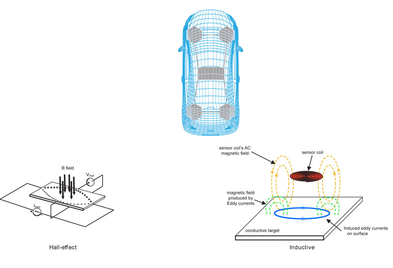
A magnetic position sensor works with Hall sensing elements and a permanent magnet mounted on the moving part. As the magnet changes position, the sensor reads the variation in the magnetic field and converts it into position data. This makes magnetic sensing compact, flexible, and easy to integrate into many modern designs.
Inductive sensing works in a different way. Instead of using a magnet, it relies on excitation and receiver coils and detects how a conductive target changes the electromagnetic response. That makes it especially useful when the target is metallic and the application benefits from short-range, very stable sensing.
Neither approach is universally better. The real question is what the system needs.
The target usually tells you a lot
One of the first things to look at is the target itself.
If the moving part is metallic and conductive, inductive sensing can be a very strong option. If the design can use a magnet, magnetic sensing opens up more freedom in terms of surrounding materials and mechanical layout. This is especially helpful when sensing needs to happen through plastic, aluminum, or other non-metal barriers.
That detail may sound small, but in real product design it changes a lot. A sensor that works cleanly through a cover or inside a sealed housing can simplify the whole assembly.
Accuracy is important, but integration is just as important
Inductive sensing can achieve excellent precision in the right setup. Some architectures are designed for very fine measurement and can deliver impressive linearity and repeatability. LVDT-style and eddy-current approaches show just how far inductive sensing can go when accuracy is the priority.
Magnetic sensing may not always win on the most extreme laboratory figures, but that is not the full story. In an actual product, performance depends on alignment, tolerances, shaft runout, thermal behavior, contamination, available space, electronics, and calibration strategy. A sensor that is slightly less ambitious on paper but much easier to integrate often gives the better result in production.
That is one reason magnetic sensing is so attractive in many OEM applications. It often delivers the right level of precision together with a simpler mechanical concept and a smaller electronics footprint.
Compact design matters more than ever
This is where magnetic sensing often stands out.
Inductive systems can require custom coil layouts and more board area. Magnetic sensors are commonly built around compact ICs and can fit into very small packages. They also support a broader range of electrical interfaces, which gives designers more flexibility when integrating the sensor into the full control system.
For many applications, that makes a real difference. Smaller electronics can mean:
- easier packaging
- simpler sealing
- lower assembly complexity
- better fit in tight housings
- a cleaner path to scaling across product platforms
Why magnetic sensing is often the more practical choice
Magnetic sensing tends to feel more natural in applications where the design team wants a compact, durable, and easy-to-integrate solution.
It is particularly well suited when:
- sensing must happen through non-metal materials
- the module needs to be sealed
- the available space is limited
- the mechanics should stay simple
- long life without wear is essential
There is another practical advantage. Modern magnetic sensor platforms are no longer limited to simple analog outputs. Depending on the product family and application, they can also support digital communication options, including CAN-based outputs such as CAN J1939 or CANopen, which are especially valuable in mobile machines, industrial equipment, and systems that need more robust networked communication.
That matters because position sensing today is rarely just about measuring movement. The sensor often has to fit into a wider electronic architecture, share data with a controller, support diagnostics, and simplify system integration.
Inductive sensing still has a very important place
None of this reduces the value of inductive technology.
Inductive sensing remains an excellent choice when the application is built around a metallic target, when short-range precision is critical, or when the operating environment strongly favors a coil-based architecture. It is also a natural fit in some factory automation systems, robotic joint monitoring, resolver-replacement concepts, and other applications where metallic targets and high precision go hand in hand.
In other words, inductive sensing is not the alternative because it is older or more specialized. It is the right answer when the mechanics and the sensing principle line up properly.
Real applications are what decide the winner
Different applications naturally lean in different directions.
Electric power steering can work with either technology depending on the design priorities. Hydraulic pump motors and chassis position sensing often align well with magnetic sensing, while traction motor environments can favor inductive solutions. In industrial applications, factory automation and robotic joint monitoring often point toward inductive sensing, while conveyor position feedback can be an excellent fit for magnetic sensing.
That is why sensor selection should never be reduced to a simple checklist. The right choice comes from understanding the whole system:
- what is moving
- what materials surround it
- how much space is available
- how the signal will be used
- what level of sealing and durability is needed
- whether the application needs analog simplicity or digital communication
In many cases, it is not about chasing the most extreme specification. It is about delivering the best overall fit. A sensor that is compact, robust, sealed, easy to mount, and available with the right electrical output, including digital network options where needed, often creates more value than a technically impressive solution that is harder to package or scale.
Inductive and magnetic sensing are both excellent technologies. The better one is simply the one that fits the job better.
If the application revolves around metallic targets and specialized short-range precision, inductive sensing may be the stronger route. If the project needs compact packaging, easier integration, operation through non-metal barriers, and the option to move toward richer digital outputs including CAN-based communication, magnetic sensing is often the more practical and scalable choice.