Advanced Current Sensing and Machine Learning in Battery Management Systems for Material Handling Equipment

The performance and operational longevity of Lithium-ion and advanced lead-acid battery systems in material handling equipment (MHE) depend on the precision of the Battery Management System (BMS). Current transducers serve as the primary sensory organs for the BMS, providing the data required for monitoring charge and discharge cycles, safety protocols, and advanced state estimation. As warehouses evolve toward 24/7 autonomous operation, the demands on BMS accuracy, thermal resilience, and predictive capability have never been higher.
Physics and Fundamentals of Hall-Effect Sensing
Hall-effect current sensors operate on the principle that a magnetic field perpendicular to a conductor carrying a current generates a voltage (the Hall voltage) across the conductor. In a current transducer, the primary current Ip flowing through a busbar or wire creates a proportional magnetic field. A magnetic core concentrates this field onto a Hall-effect element.
Two primary Hall-effect topologies are deployed in MHE applications:
- Open-loop sensors are simpler and lower cost. The Hall element directly transduces the magnetic field into a voltage. They are well-suited for sub-module or auxiliary monitoring where absolute accuracy is secondary.
- Closed-loop (compensation) sensors use a feedback coil to null the magnetic field at the Hall element, driving the net flux to zero. This dramatically reduces offset drift and nonlinearity, achieving accuracies better than ±0.5% over the full temperature range — essential for accurate State of Charge estimation in high-value traction packs.
Unlike shunt resistors, Hall-effect sensors are non-intrusive. They do not require a physical break in the circuit and do not suffer from the power dissipation (P = I^2R) that leads to significant heat generation in high-current MHE applications. Furthermore, they provide inherent galvanic isolation between the high-voltage traction circuit and the low-voltage control electronics, which is a critical safety requirement — particularly as traction voltages climb above 48V toward 80V and 96V systems.
Mathematical Modeling of Sensor Performance
Engineers must model transducer behavior to ensure accuracy across the battery’s entire operating range. The transfer function for a linear Hall-effect sensor is:

Error Analysis and Thermal Drift
In battery cycling, the most significant challenge is offset drift over temperature. The error ɛ is modeled as:
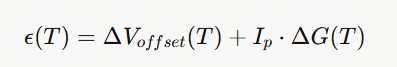
Precision systems utilize hardware compensation or software-based look-up tables to nullify these errors during the battery’s thermal cycles. A more complete error budget for MHE applications must also account for:
- Remanence error: After exposure to a high-current transient (e.g., a forklift mast lift), residual magnetization in the core can offset subsequent readings. Demagnetization routines triggered during open-contactor intervals mitigate this.
- External stray field error: Nearby motor windings and inductors generate fields that couple into the sensor’s aperture. Quantified as an equivalent current error (e.g., ±2A per mT of stray field), this must be evaluated during mechanical layout.
- ADC quantization noise: At 12-bit resolution over a ±600A range, each LSB represents ~0.29A. Upgrading to 16-bit ADC resolution reduces this to ~18mA, directly improving Coulomb-counting fidelity over long cycles.
Bandwidth and Dynamic Response
For regenerative braking and mast-lift transients, sensor bandwidth is critical. A sensor with a 3dB bandwidth of 100kHz can resolve current rise times well under 10μs, enabling the BMS to react before an overcurrent condition propagates to the cell level. Closed-loop sensors typically outperform open-loop designs in bandwidth, making them preferred for high-dynamics applications.
Machine Learning for SOC and SOH Estimation
While traditional Coulomb counting is the baseline for State of Charge (SOC) estimation, it is prone to integration drift. Modern MHE systems leverage machine learning (ML) to capture the complex, non-linear degradation of Lithium-ion cells.
The Limitations of Coulomb Counting
Coulomb counting accumulates charge:![]()
The Coulombic efficiency η is never exactly 1.0, and Qnom degrades with each cycle. Small sensor offsets compound over a shift, meaning a forklift starting a second shift with an inaccurate SOC reading may be denied a full work cycle or, worse, discharged into the irreversible low-voltage region. ML-based correction loops are the primary remedy.
Architectural Taxonomy
1. Gated Recurrent Architectures (LSTM/GRU)
Long Short-Term Memory (LSTM) networks use gates to regulate information flow, allowing the model to retain long-term degradation trends while discarding measurement noise. Gated Recurrent Units (GRU) offer a simplified alternative with lower computational overhead — an important consideration for deployment on ARM Cortex-M class microcontrollers. A GRU model with 32 hidden units and INT8 quantization can achieve SOC estimation within ±1.5% RMS while running comfortably within a 64KB RAM budget.
2. Convolutional-Recurrent Hybrids (CNN-LSTM)
1D-CNN layers act as feature extractors for local patterns in voltage and current transients (e.g., the characteristic voltage plateau shift indicating a lithium iron phosphate cell entering its flat region), which are then processed by LSTM layers to model temporal evolution over thousands of cycles.
3. Transformers and Attention Mechanisms
Self-attention weights the importance of different time steps simultaneously. Rate-Aware Attention can adaptively focus on high-current discharge periods where voltage drops are most significant and information content is highest. The primary deployment challenge is computational cost: transformer inference latency must remain under the BMS control loop cycle time, typically 10–100ms.
4. Ensemble and Hybrid Physics-ML Models
A growing deployment pattern pairs a fast physics-based equivalent circuit model (ECM) for real-time SOC tracking with a slower ML model that corrects ECM parameters (internal resistance, open-circuit voltage curve) as the cell ages. The ECM provides physical interpretability and safe behavior; the ML component provides long-term accuracy.
Physics-Informed Machine Learning (PIML)
To prevent “black box” models from producing physically impossible results, electrochemical constraints are embedded directly into the loss function:
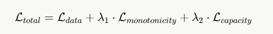
Where the monotonicity penalty penalizes any increase in predicted SOH during a discharge event, and the capacity constraint bounds SOC predictions within [0, 1]. This ensures that predictions respect the irreversible nature of battery aging even when the model encounters out-of-distribution operating conditions.
Feature Engineering
ML model performance is optimized through deliberate feature extraction:
- Incremental Capacity (IC) Analysis: Extracting peaks from the dQ/dV curve. Peak positions shift predictably with lithium inventory loss; peak heights correlate with active material degradation. Automated peak tracking across cycles provides a powerful aging biomarker.
- Differential Voltage Analysis (DVA): The inverse view (dV/dQ curves) is particularly sensitive to structural degradation in graphite anodes and cathode phase transitions.
- Voltage Relaxation: Monitoring the stabilization rate after load removal to determine internal resistance. The time constant of relaxation is directly related to solid-electrolyte interphase (SEI) growth.
- Statistical Moments: Analyzing the variance and skewness of temperature fluctuations during rapid charging — non-Gaussian temperature distributions often indicate localized cell degradation or cooling system degradation.
- Partial Charge Signatures: In opportunity-charged AGV fleets, the BMS rarely observes a full charge cycle. Models trained on partial-charge sequences using dynamic time warping alignment have shown resilience to this operational constraint.
Electrical Integration and System Architecture
A typical integration scheme involves placing the transducer on the main negative or positive busbar of the battery pack.

Signal Chain Design
Signal Conditioning: The analog output is passed through an RC low-pass filter to eliminate high-frequency noise from the motor controller PWM switching (typically 8–20kHz for IGBT inverters). The filter corner frequency should be set at least one decade below the switching frequency — a 1kHz cutoff is common — while remaining well above the maximum expected current slew rate. A differential instrumentation amplifier stage then rejects common-mode noise picked up along the cable run.
ADC Acquisition: The filtered signal is sampled by the BMS microcontroller using a 12-bit or 16-bit ADC. Oversampling and decimation (e.g., averaging 16 samples at 12-bit yields 14 effective bits) is a cost-effective technique on microcontrollers with fast SAR ADCs. Synchronization of ADC sampling to the inverter’s PWM dead-time can further reduce switching noise ingress.
EMI Mitigation: Differential signaling is preferred for cable runs exceeding 300mm between sensor and BMS. Twisted-pair wiring with a drain shield, grounded at a single point, suppresses both electric field coupling and magnetic induction. For the most noise-sensitive installations, CAN-based sensor interfaces (e.g., current transducers with an integrated CAN output) can entirely eliminate the analog cable run.
Communication Interfaces: The BMS MCU communicates with upstream systems over CAN bus (ISO 11898), SMBus/I2C for battery pack identification, or RS-485 in legacy deployments. Modern fleet management systems increasingly rely on BLE or LTE-M uplinks to stream SOC, SOH, and fault logs to cloud platforms for predictive maintenance scheduling.
Cell-Level vs. Pack-Level Monitoring
An important architectural choice in BMS design is the granularity of monitoring:
- Pack-level monitoring uses a single transducer on the main busbar. It is cost-effective and sufficient for single-chemistry packs with matched cells. The HCSP-1BS is optimized for this role.
- Module-level monitoring adds transducers to each parallel cell group. This enables detection of inter-module imbalances caused by partial tab weld failures or differential aging, which pack-level monitoring cannot distinguish from normal variation.
- Cell-level monitoring (emerging in high-criticality applications) places sensing at each cell string. Combined with electrochemical impedance spectroscopy (EIS), it allows early detection of lithium plating and separator degradation — failure modes with serious safety implications.
The HCSO-1W’s compact form factor makes it well-suited for module-level deployment in larger battery enclosures, where a bank of sensors feeds a multiplexed ADC front-end.
Use Cases in Material Handling Equipment

Dynamic Load Monitoring in Forklifts
Electric forklifts experience extreme current fluctuations during mast lift operations — full-load lifts can demand 600–800A bursts from a 48V pack. Current transducers must have a high dynamic range and fast response time (typically < 5 milliseconds ) to capture these transients, preventing voltage sags from triggering system resets. The BMS uses these transient profiles to apply dynamic power derating: as temperature rises or SOC drops, the permitted peak current is progressively reduced to protect cell integrity while maintaining safe operability.
Opportunity Charging in AGVs
Automated Guided Vehicles often use short bursts of “opportunity charging” at inductive or conductive docking stations — typically 5–15 minute charges at 1–3C. Precise current monitoring ensures the charger stays within the battery’s maximum C-rate, preventing lithium plating on the graphite anode. The BMS also uses these frequent partial-charge events to apply incremental SOC corrections, preventing the drift that would otherwise accumulate over a 16-hour multi-shift operation.
Regenerative Braking Energy Recovery
In reach trucks and counterbalanced forklifts, lowering the mast regenerates energy back into the battery. The BMS must accurately measure and integrate regenerative current — which flows in the opposite direction to discharge — to maintain SOC accuracy. Hall-effect sensors’ bidirectional linearity and zero insertion loss make them directly suited to this application, unlike shunt-based designs which require additional circuit complexity for bidirectional operation.
Multi-Shift Fleet Management
Large distribution centers operate fleets of 50–200 MHE units continuously. Cloud-connected BMS units upload per-cycle data (energy throughput, peak temperature, maximum C-rate) which fleet management software uses to schedule battery swaps, flag units approaching end-of-life (SOH < 80%), and optimize charging windows to minimize peak grid demand.
Implementation Tips for Engineers
- Magnetic immunity: Place the sensor away from stray magnetic fields produced by motors or large inductors. Use magnetic shielding if proximity is unavoidable. Validate immunity by measuring sensor offset with the adjacent motor running at no-load current.
- Aperture centering: Ensure the primary conductor is centered in the sensor aperture to maintain linearity — off-center positioning introduces a position-dependent gain error that cannot be corrected in software.
- Zeroing: Implement a zero-current calibration routine in the BMS firmware that executes when contactors are open. Re-execute after each full charge to compensate for temperature-driven offset shifts.
- Remanence recovery: Add a brief alternating demagnetization pulse sequence in the open-contactor window to clear residual magnetization in the core following high-current transients.
- Model compression: Use weight pruning and INT8 quantization to deploy ML models on industrial microcontrollers. A well-pruned GRU model typically retains >95% accuracy at 30–40% of the original parameter count.
- Fault injection testing: Validate BMS safety responses by injecting simulated sensor faults (open circuit, stuck-at-rail) in a hardware-in-the-loop (HIL) environment before field deployment.
- Calibration traceability: Maintain a per-unit calibration record linking each transducer to its factory trim constants. This enables residual error correction in firmware and supports warranty root-cause analysis.
Specific OEM Hardware Solutions
HCSP-1BS (Busbar Series)
The HCSP-1BS is designed for high-capacity traction batteries. It mounts directly onto a copper busbar and is ideal for main battery outputs where currents exceed 500A. Its robust housing is built for the vibration-heavy environments of reach trucks and counterbalanced forklifts. Key design considerations when deploying the HCSP-1BS include busbar cross-section matching (to maintain correct insertion impedance) and thermal bonding between the busbar and sensor housing to minimize differential thermal expansion over the operating temperature range.
HCSO-1W (Open-Loop Wire Series, Dual Channel)
The HCSO-1W is a compact sensor for wire-through or PCB integration. It is best suited for sub-module monitoring, integrated charging units, or smaller MHE such as powered pallet jacks and AGV control boards. Its low profile and PCB-mount footprint simplify integration into space-constrained BMS assemblies. Both sensors provide a 0.5V to 4.5V output range and maintain 2.5kV+ galvanic isolation required for high-voltage battery safety compliance.
Selection Guide
| Parameter | HCSP-1BS | HCSO-1W |
|---|---|---|
| Primary topology | Busbar mount | Wire-through |
| Current range | Up to ±1500 A | Up to ±1,000 A, Dual output |
| Best application | Main pack output | Sub-module, AGV control |
| Vibration rating | High (reach trucks) | Moderate |
| Isolation | 2.5kV+ | 2.5kV+ |
| Output | 0.5–4.5V | 0.5–4.5V |
Regulatory and Safety Context
BMS designs for MHE must comply with several overlapping standards:
- IEC 62133 / UL 2580: Cell and battery pack safety for industrial applications.
- ISO 13849 / IEC 62061: Functional safety of machinery — relevant when BMS outputs control machine actuation (e.g., contactor opening on overcurrent).
- UN 38.3: Transportation testing for lithium cells, which informs thermal runaway resilience requirements.
- OSHA 29 CFR 1910.178: Occupational safety standard specific to powered industrial trucks, which mandates safe charging procedures and battery maintenance intervals that a compliant BMS must support.
Galvanic isolation at the current transducer interface directly supports the creepage and clearance requirements of these standards, and should be verified against the specific working voltage of the traction pack.